Boring for pressuremeter tests using a self-drilling split tube system (STAF)
Gérard ARSONNET, Geomatech, Champlan - France
Jean-Pierre BAUD, Eurogeo, Avrainville - France
Michel GAMBIN, Apageo, Magny les Hameaux - France
Summary
Following on from Louis Ménard's research and development, several of his colleagues, in association with younger geotechnicians, have sought a way of creating the cavity into which the pressuremeter probe is to be inserted using the most recent drilling techniques, the procedure remaining globally economical. The proposed cavity is virtually free of reworking and the surrounding soil free of relaxation. Comparative examples are provided in a wide range of soils.
Introduction
From the very beginning of the use of the pressure meter, Louis Ménard and his first collaborators were confronted with criticism from geotechnical experts who were sceptical about the representativeness of the tests in different types of soil. The first users therefore had to define the drilling and testing conditions that gave the most reliable results. The role of good borehole wall retention and the availability of a cylindrical cavity well calibrated to the diameter of the probe soon became essential (PLM, 1962). The use of the hand auger, at shallow depth, in dry conditions in predominantly clay soils above the water table, or with bentonite circulation, thus became the archetypal quality test. The probe could be introduced shortly after drilling into a well-cut, smooth-walled hole, in which contact with the ground was obtained in the first few steps without any trace of reworking (LCPC 1971). The geotechnical drilling machines of the 1960s were mainly mechanically driven and built for core drilling. Louis Ménard and his collaborators initially produced pressuremeter probes with diameters adapted to 3'', 3½'', 4'', 4½'' and even larger corers. The handling and installation times of the probe were too long and favoured the decompression of the excavated soil with core drill type tools. It was therefore not long before probes with smaller diameters, 32mm (1¼''), 44mm (1¾''), 63mm (2½''), were used for hand augering or by beating a core drill. Early on, Louis Menard (1959) patented the split tube for direct driving of the probe in granular soils below the water table, where the cavity walls are difficult to maintain without slumping. Hydraulic vibro-driving machines were also designed and produced to use this split tube, mainly in marine environments (Ménard and Gambin, 1965). A second problem was, and still is, crucial, that of the downtime associated with carrying out the tests of an "authorised pass" according to the standard: the time spent raising the drilling tool after each pass, then the time spent lowering the probe to carry out the test, and finally the time spent raising the probe and lowering the drilling tool. It was with the aim of solving these problems of dead time that new research was launched, which led to the filing of a patent that contained the seeds of the process we are about to present (Ménard 1976). The concept of self-drilling of a tube, here by "back-jet", possibly associated with a cable ramming using a slender ram, sliding in the lower part of the tube, and that of a pressure meter probe permanently placed in line with the split part along several generators of the tube (figure 1), are all present.
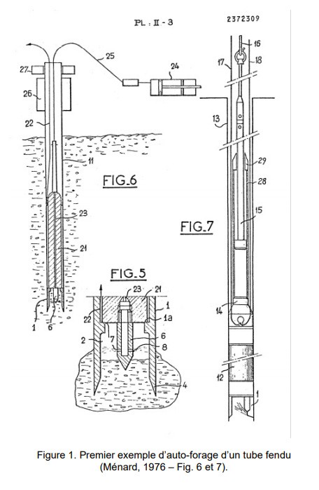
The method described in the patent made it possible to do away with the notion of a permitted drilling pass, as the walls of the borehole are always maintained while the tests are carried out when the pipe is brought up, and to eliminate the time spent handling the drilling tool. However, this technique is only applicable to soft soils, unless you have very high-pressure jet-cutting equipment that is still not very handy on small geotechnical study sites.
The split or "lanternized" tube
There are many drilling methods for creating a cavity that is compatible with a reliable pressuremeter test, but they are generally associated with a well-defined soil type (AFNOR, 2000). Amongst these, let us return to those that involve a "split" tube. The split tube - or "lanternized" tube, which is more explicit - whose diversity of diameters has become rarer, favouring the 63 mm (approx. 2½'') diameter, is currently used in 3 ways whose principle is radically different: - As a "direct split tube": the split tube, closed at its end by a spike (preferably at the end of a tube coupon) or a corer is driven directly, by ramming, vibro-drilling or jacking, with a 44 mm diameter pressuremeter probe fixed inside; It is the equivalent of the "drilling" tool used before the test, more exactly the tool for creating the test cavity, the temporary densification of the soil in the vicinity of the point being re-equilibrated by the subsequent vibrations in the sands embedded at the level of the tube slots (TLM, 1966); the length of the passes has no limit, that of the drilling is limited by the refusal of the ramming. - As a Chinese lantern tube in a previously drilled hole: used as a protection for an AX (44 mm) probe instead of a BX (60 mm) probe, the whole constitutes a probe used in a borehole with walls either poorly maintained or partially maintained by a column of drilling mud; the resistance of the tube to the aggressiveness of the soil of the walls, generally heterogeneous, makes it possible to carry out a calibrated drilling more "tightly" than for a flexible sheath probe, the reduction in diameter being able to go down to a value lower than that of the probe, which leads to the technique known as the pilot hole, intermediate between a true preliminary drilling and the use of a direct split tube; the length of the passes is limited according to the standard according to the type of ground tested. - As an "open" split tube operating as a corer, the cut material is removed either after each phase of beating of limited duration by lowering an ad hoc tool, or simultaneously by permanent back-jet nozzles at the base, the ascent of sediments being ensured by the injected flow, or by an internal destructive rotary tool with mud circulation; the length of the passes has no limit, except that of maximum penetration under the effect of the friction on the tube. The latter technique, although very attractive from a conceptual point of view, has been less and less practised, due to the increasing availability of multifunctional drilling machines, to the point where it has almost disappeared, although the pass length limit imposed by the relaxation of the ground has become irrelevant. It disappeared from the table of methods between the pressiometric procedure (LCPC, 1971) and the first publication of the French standard (AFNOR, 1991), and is referred to in the current version (AFNOR, 2000) as "split tube with simultaneous removal of materials" by the acronym TFEM. This technique is also described and allowed in the American standard (ASTM, 1987) in § 7.4.2.9 under the title "Pilot Hole Drilling and Simultaneous Shaving": "drilling with a pilot tool of smaller diameter than the probe and shaping the cavity with a thin hollow cylinder located just above the tool and linked to the drill string. The pilot tool and the tube are pushed with a thick slurry flow. Could we go further than these descriptions and, by increasing the penetration of the tube without limit, reduce the time required to raise and lower the drilling tool between test periods?
Self-drilling of the split tube or STAF
On the basis of these data, the authors of this paper have endeavoured to develop a unique drilling method, whatever the type of soil, which allows reliable pressuremeter tests to be carried out, with the reworking of the borehole walls being reduced to a strict minimum and remaining virtually the same whatever the soil. We thus sought to optimise the two parameters influencing the shape of the beginning of the pressuremeter curve: - the "reworking" of the borehole walls themselves, by seeking a technique for cutting the ground quickly, uniquely and precisely in its calibration, perfectly cylindrical and ensuring rapid and complete evacuation of the sediments; - the decompression of the surrounding soil, a phenomenon which begins as soon as this cutting is carried out and whatever its quality, by ensuring the support of the borehole wall by a tube of the exact calibre of the probe in a few fractions of a second after the cutting of the ground.
The material
The necessary equipment is chosen so that it can be used by any type of hydraulic drilling machine allowing roto-percussion coupled with the circulation of a drilling fluid. It includes, in the version used for the results presented in chapter 4 below, the following elements
- a fitting to connect the rotopercussion head fitting outlet with the R32mm cord type rods, it is enlarged to press on a beater head;
- a metal 'martyr' washer (consumable) on the threshing helmet;
- the 63 mm inner diameter battering helmet, equipped with a drilling fluid discharge chute;
- a set of 122 mm long extension rods in 32 mm diameter, and roto-percussion sleeves, a classic piece of equipment which must nevertheless be robust against roto-percussion;
- a set of tubes with an external diameter of 63 mm and an internal diameter of 49 mm, in 122 mm long elements, screwed together without protrusion with a pitch designed to behave well under the vibration of the roto-percussion hammers;
- a split tube with an external diameter of 63 mm and an internal diameter of 49 mm placed at the foot of the tube-stem assembly, equipped at its base with an open shoe and a reservation for positioning the probe;
- a destructive roto-percussion tool guided by the casing shoe, "extendable" to the drilling diameter and retractable into the casing; this is a further development of the known retractable Odex® type tools in larger diameters, its diameter being calibrated so as to drill a hole adjusted to that of the casing used; - a system for gripping the casing above the jacks, consisting either of a self-tightening collar or a hydraulic ring anvil;
- a system for lifting the casing by hydraulic jacking upwards;
- an AX type pressuremeter probe with an external diameter of 46 mm, fitted with a special tip with mobile fins allowing it to be positioned precisely in the middle of the slotted section of the tube and to be withdrawn at the end of the tests;
- Finally, the pressure-volume pressuremeter, preferably with electronic recording of readings.
How it works
The sequence of operation of this assembly is described in the diagram in Figure 2. The casing string descends at the same speed as the drilling tool performing a true self-drilling of the split tube, which forms the protective and expandable envelope of the probe which will then be positioned at its level. The self-drilling of the casing is characterised by the fact that the destructive "expandable" tool extends beyond the base of the casing and moreover occupies the whole of the master tube. Although this is a departure from the principle of strict self-drilling of the tube, this defect is largely compensated for by the possibility of drilling continuously without changing the tool in all types of soil, from fine compressible soils to steep, stony soils and even directly in rock or alternating soils and cemented rock. The result is a standardised reshuffle reduced to a minimum by the possible decompression of the ground during the second or fraction of a second between the cutting by the protuberant tool and the arrival of the casing. Particular attention is paid in this system to the evacuation of the cuttings, which are pushed towards the interior of the casing by the shape of the tool itself and by the direction given to the injection nozzles, which only attack the ground frontally and favour the ascent of the loaded fluid into the casing shoe where they are crushed to a sufficiently fine granulometry to make this ascent easier. The circulation fluid, which can be based on bentonite, a classic but less and less used in practice by drilling workshops that have too little time left on a drilling site to prepare a sufficiently swollen bentonite mud, can also be a polymer mud that can be prepared almost instantaneously. The advantage of this is that the polymer mud is not required to line the borehole walls, with which it has virtually no contact except between the drilling tool and the casing shoe, but primarily to have the necessary viscosity to coat the sediments and bring them up completely. All the mud can be collected in the chute at the exit of the driving helmet, which allows the drilling supervisor to visualise its continuous and regular exit, and to have it immediately sedimented with the possibility of taking at each pass a part of the cuttings which can be put in bags for a cuttings cut, in a very clean way. The drilling site around the hole also remains very clean, and decanting in an appropriate tank (or double decanting) allows the discharge of a sediment-free drilling liquid. At the end of the drilling process, the volume of sediment precipitate crushed in the bottom of the tube is relatively concentrated and can be used, with the possible addition of a small percentage of cement, to make a grout to be re-injected to plug the borehole, guaranteeing both a waste-free drilling site and a tight plugging of the borehole.

Presentation of some test results
We will present test results for the open split tube and the STAF® self-splitting tube. We will analyse the specific qualities of the method and compare the pressuremeter results with other drilling methods.
Focus
The first development of the 63 mm eccentric retractable drilling tool was done from 2000 to 2003 and the first drillings with this tool in 2003. The first drillings were attempted in different soils to check the difficulties of lowering and raising the pipe depending on the diameter of the tool. It turned out that a tool a few millimetres larger than the diameter of the pipe allowed the casing string to be lowered quickly and easily, but led to tests with a contact volume that was too high and disturbed, because the annular space, however small, tended to cause the spoil to rise up and form a plug around the split pipe. The tests at Bruyères le Châtel, borehole FP3 of the Teratec project, with a ballistic button tool illustrate this problem: the tests are interpretable, but the E/Pl ratio seems to be overestimated in comparison with neighbouring tests in pre-drilling with mud, which moreover may not represent the "true" pressure modulus of the ground, which is probably intermediate. Obtaining tests that conform to the expectations of the method came fairly quickly by observing the following provisions:
- use of a 65mm diameter tungsten carbide insert tool
- moderate injection pressure not exceeding 2 MPa on average
- moderate injection rate also 30 to 60 l/min
- fairly low percussion frequency: in fact the percussion frequency, which varies according to the type of impact which differs according to the hammer models, is the element that the driller can modulate according to the terrain: a few rare blows (less than 30 blows/min) in compressible ground and up to limit pressures of the order of 1 MPa, where the descent of the tube-rod assembly is rapid; increase in frequency up to 60 to 100 blows/min in medium to steep ground, up to PLM of 2 to 3 MPa; beyond that, one enters steep to very steep ground, where it is necessary to increase the frequency, which can reach 300 to 500 blows/min according to the type of striker, and the thrust on the tool to keep a sufficient penetration speed;
- Monitoring the rate of flow of the drilling fluid loaded with cuttings is essential for the driller, any tendency to decrease the flow rate corresponds to a risk of "blockage" which must be compensated for immediately by a controlled increase in the injection rate, which sets the fluid in motion again;
Drilling under these conditions achieves the desired result of a perfectly cylindrical and vertical hole quite well: the well-guided drilling tool completely destroys the ground, and the rigid edge of the casing shoe crushes the wall in case fragments of soil remain, setting up with a certain friction corresponding to the adjustment to the hole diameter. Extraction is relatively difficult from a certain depth: it generally exceeds the pulling force of standard geotechnical drills and requires the use of a jacking system. This, together with the absence of risers around the casing, ensures that the goal of perfect ground adjustment around the casing has been achieved, without decompression but also without the risk of backflow. From the point of view of work organisation, we used either the well-known system of jacks on a ring anvil taken and adapted from the D9000 Ménard drilling machine for the extraction of the "direct" split tube, or a ring jack operated by the drilling workshop. But it is quite possible, and this is one of the advantages of the method, to divide the work between a workshop for self-drilling the split tube, leaving its string of casings in place before moving on, and a pressuremetering workshop carrying out the extraction of the casing and the recording of the tests during the ascent, either immediately afterwards or with a time lag imposed by the circumstances of the site (roadways in traffic with limited interruption, for example)
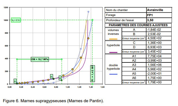
Examples in different soil types
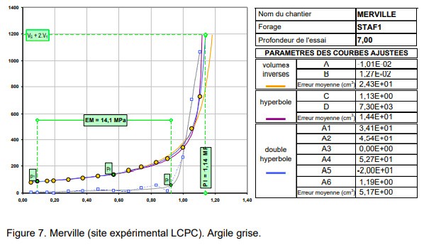
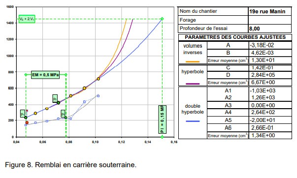
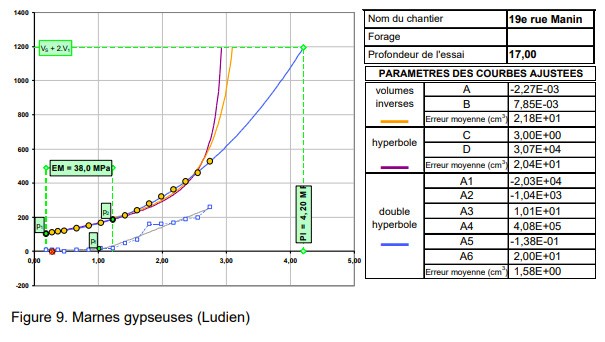
The test curves below show different types of soils and values of moduli and limit pressures. Apart from the Avrainville development tests and the Merville LCPC experimental site, the tests were carried out on real construction sites, G0 missions followed by G1 and later missions.


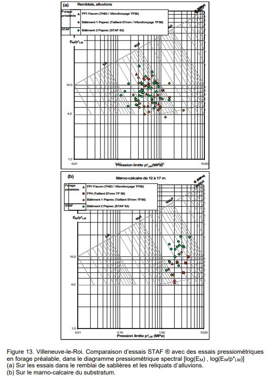
Comparison with pre-drilled tests without casing
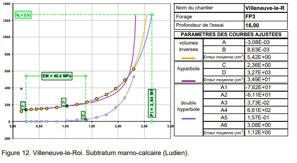
The Villeneuve-le-Roi drilling campaign is particularly interesting, because it consists of 3 drillings from 15 to 18 m for the construction of a warehouse (on piles) in a site where a previous warehouse (Paprec company) and a stamping press were built nearby on pressuremetering campaigns with prior drilling. Comparison of the results (figure 13) shows that in the recent fill and alluvium of this site, up to about 11 m, the distribution of the EM and pLM values of the tests, if they differ in detail, is statistically little different. In contrast, in the marl to marl-limestone bedrock, the STAF tests show, for a comparable limiting pressure, better grouped and higher EM/pLM ratios; in this case, it is certain that these modulus values are closer to the reality of the field, and that the previous values in pre-drilling had slightly underestimated the moduli.

Conclusions and perspectives
The tests presented above correspond, after a period of development, to some 15 full-scale sites at various depths up to 22 m at present; drilling to 45 m is planned. The results are sufficiently encouraging that it is already certain that the influence of drilling on the initial phase of the test is greatly reduced. The development of drilling and vibratory hammering tools is continuing with the aim of enabling tests with negligible initial reworking to be carried out in all types of soil.